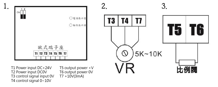
Terminal block Pin Description:
1. T1 DC + 24V power input
2. T2 power input DC0V
3. T3 control signal input 0V
4. T4 control signal 0 ~ 10VV
5. T5 output + V
6. T6 output 0V
7. T7 + 10V (3mA) (when the device need an external variable resistor, can use this voltage wiring pin wiring, refer to Figure 2)
pin wiring diagram:
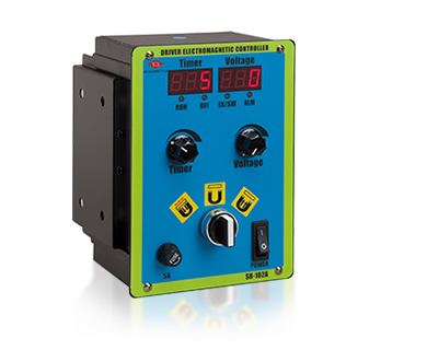
Potentiometer adjustment Description:
1. VR1: Imax current intensity multiple ratio value adjustment, increased clockwise.
2. VR2: Imin, staring current value intensity adjustment,increased clockwise.
3. VR3: UP Time,up time slope adjustment 0.1 ~ 5S, increased clockwise.
4. VR4: DN Time, down time slope adjustment 0.1 ~ 5S, increased clockwise.
5. VR5: Frequence frequency value adjustment, 80~500HZ increased clockwise.
SINA-A single set of hydraulic proportional valve selection model specifications SINA-A - Code 1
| Code1 |
|---|
| BOX |
Circuit control panel is equipped with outer protecive box. |
| BLK |
Circuit control board is equipped with Z-shaped bracket. |
.png)
.png)
.png)
.png)
.png)
.png)